|
Construction diagrams and photographs taken during the test build |
Click pictures to view full size |
||||||
|
|
|
||||||
|
|
|
||||||
|
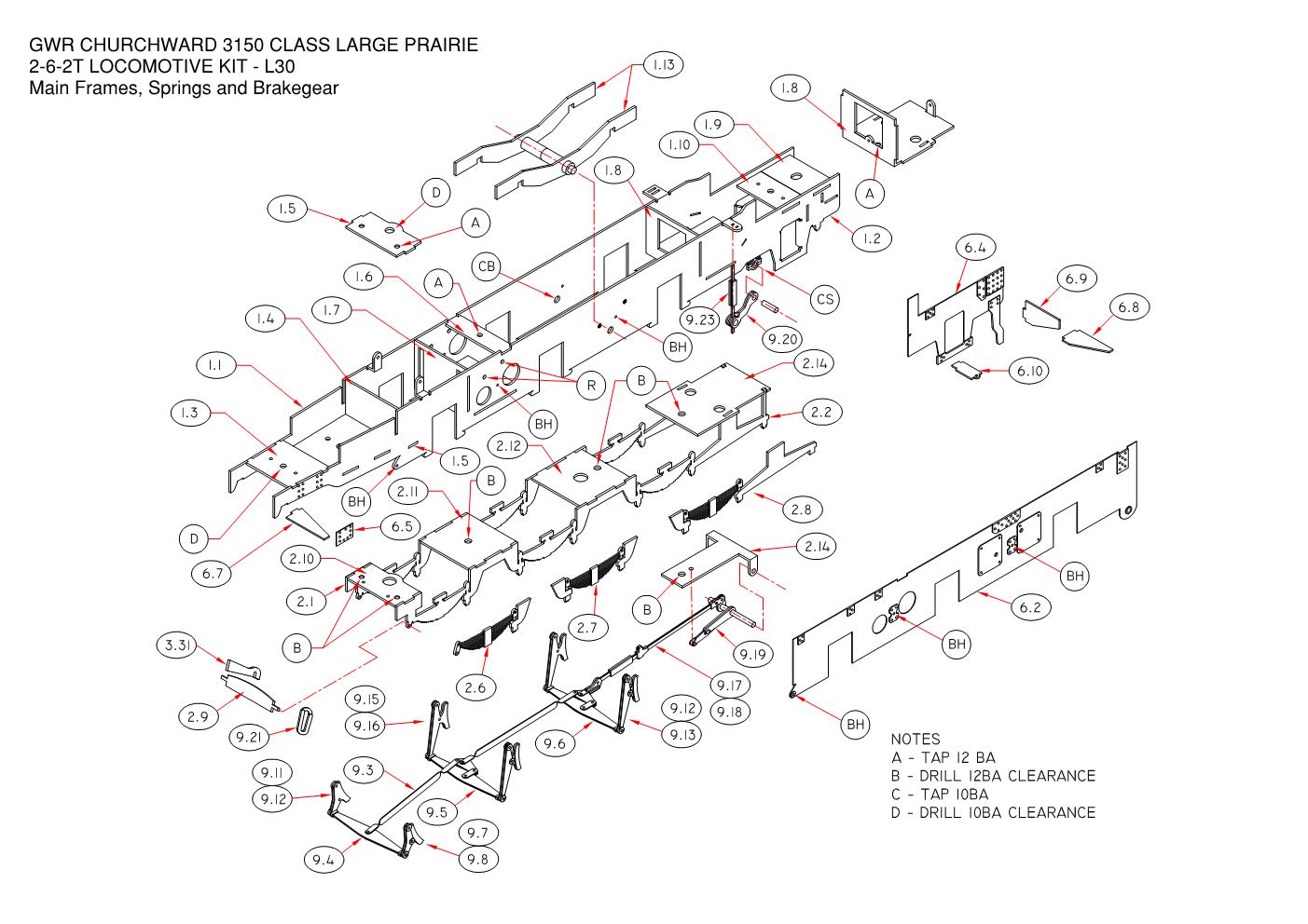
Mainframes |
Footplate and cab floor |
Boiler, tanks and bunker |
Pony truck and cylinders |
||||
|
|
|
||||||
|
Spring and Compensation Beam Keeper Plate Assembly |
Cylinder Block with Wrappers and Valve Chest Overlays |
||||||
|
|
|
||||||
|
Coupling Rods with Alignment Jig used to accurately position the bearings and hornblocks. Note the valve rocker shaft brackets are not yet formed to shape |
Right-hand Crosshead with connection to Vacuum Pump. The brass vacuum pump casting has sinve been superseded by a resin print |
||||||
|
|
|
||||||
|
Trial Fit of Cylinder Block in the frames with the Valve Chest and Piston Rod tubing in place. Note that these tubes are over-length |
Cylinder Block, Slidebars, Piston Valve Gear and Motion Support Plate |
||||||
|
|
|
||||||
|
Assembled Pony Truck - Swing Link Version |
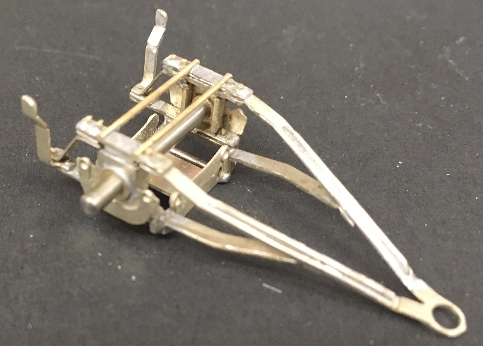
Complete Brake Gear Assembly |
||||||
|
|
|||||||
|
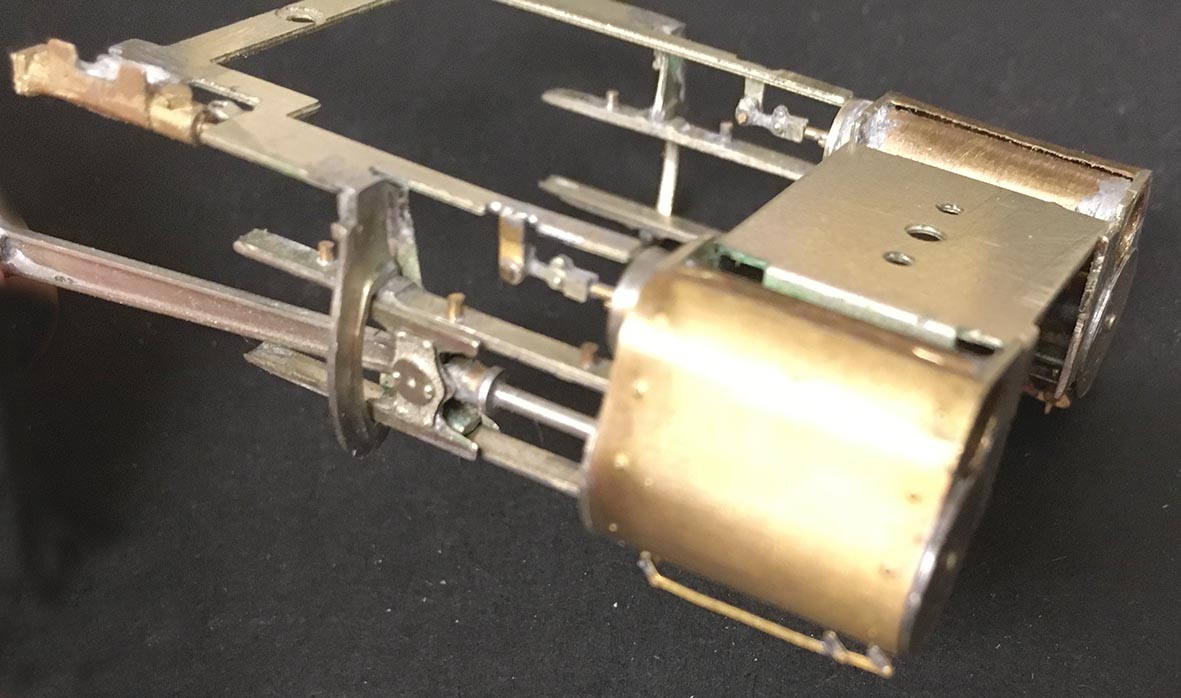
Complete Chassis Assembly almost ready for testing. Note that on this test build the Frame Overlays and Balance Weights have yet to be fitted. The High Level gearbox frame requires modification in order to drop between the frames for removal. |
|||||||
|
|
|
|
|
|
|||
|
View of tank former from the rear |
Running Plate with tank former |
Cab front and firebox in position |
Bunker former with the bunker front overlay in place. Note that the water feed valve rod guides should be horizontal. |
Smokebox and parallel boiler section with the formers temporarily held in place |
|||